
How Hardware-in-the-Loop Testing Works: Inside a Real ECU Test Workflow
Imagine developing an electronic control unit that controls a vehicle’s cooling fan. The ECU must monitor temperature, determine when cooling is required, activate the fan, and recognize electrical faults. How can engineers verify all these conditions before connecting the controller to an actual vehicle?
This is where Hardware-in-the-Loop Testing, commonly called HIL testing, becomes useful.
Instead of requiring a complete physical vehicle, engineers connect the real ECU to a test system that reproduces selected operating conditions. The ECU receives electrical signals and communication messages, executes its actual embedded software, and sends outputs back to the test environment.
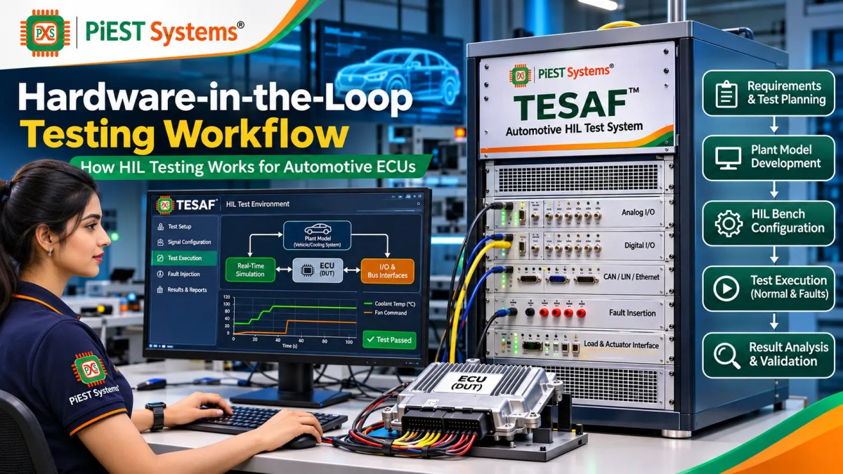
Hardware-in-the-Loop Testing makes it possible to evaluate normal operation, unusual conditions, communication failures, and software responses in a controlled laboratory.
But what actually happens inside a HIL system? Why must the simulation execute in real time? And how does the test bench determine whether the ECU has behaved correctly?
To understand the process, we need to look at the complete HIL testing workflow, from requirements and system models to test execution, fault injection, and validation reports.
1. What Is Hardware-in-the-Loop Testing?
Hardware-in-the-Loop Testing is a verification and validation technique in which a real embedded controller interacts with a simulated representation of its operating environment.
The controller under test, often called the Device Under Test (DUT), executes software on its actual processor. A separate simulation system reproduces relevant sensors, actuators, physical behavior, and external communication.
For an automotive ECU, the simulated environment may represent engine speed, vehicle velocity, battery voltage, steering angle, temperature, or signals received from other ECUs.
The important distinction is that the ECU hardware is real, while some or all of the surrounding system is simulated.
For example, a temperature sensor can be represented by an electrical signal generated by the test bench. The ECU interprets that input through its normal software and hardware interfaces.
If the ECU commands a cooling fan to turn on, the simulator detects the output and can update the simulated temperature according to a thermal model.
This creates a feedback loop between the ECU and the simulated physical system.
2. Why Was Hardware-in-the-Loop Testing Introduced?
Before modern HIL systems became widely used, engineers often depended heavily on physical prototypes, vehicle testing, laboratory equipment, and manual test procedures.
These techniques remain essential. However, they are not always practical during early embedded software development.
Consider the limitations of testing every condition in a physical vehicle:
- Some faults are unsafe or expensive to reproduce.
- Vehicle prototypes may not be available when ECU software is ready.
- Environmental conditions can be difficult to control repeatedly.
- Physical test setups may require several interconnected subsystems.
- Manual testing can be slow when hundreds of conditions must be evaluated.
- Failures may be difficult to reproduce with identical initial conditions.
Hardware-in-the-Loop Testing addresses many of these limitations by providing a controlled environment around the actual embedded controller.
Engineers can repeat a simulated vehicle event, vary input signals, introduce selected faults, and record the ECU response without reproducing every condition in a complete physical vehicle.
HIL does not eliminate road testing or physical system validation. It complements those activities by enabling earlier and more repeatable ECU testing.
3. The Basic Architecture of a HIL Testing System
A practical HIL test setup is built around several connected elements.
Real ECU or Device Under Test
The ECU runs its embedded application software on the intended controller hardware.
It may contain an automotive microcontroller, power supply circuitry, CAN or Ethernet interfaces, analog inputs, digital outputs, and actuator control circuitry.
Real-Time Simulator
The real-time simulator executes the mathematical or logical models representing the ECU’s environment.
It calculates simulated conditions and exchanges signals with the ECU within defined timing requirements.
Plant Model
The plant model describes the physical system being controlled.
Examples include a motor, vehicle dynamics, battery system, thermal system, or an engine subsystem.
A plant model may range from a simple mathematical relationship to a complex multi-domain simulation.
Input and Output Interfaces
The interface hardware connects the simulator with the ECU.
Depending on the application, it may generate or measure analog voltage, digital signals, PWM, resistance, frequency, or communication messages.
Electrical protection, isolation, signal conditioning, and appropriate loads may also be necessary.
Communication Interfaces
Automotive HIL Testing may involve CAN, CAN FD, LIN, Ethernet, or diagnostic communication, depending on the ECU.
Some systems also simulate messages normally transmitted by other vehicle controllers. This is commonly known as restbus simulation.
Test Automation and Data Acquisition
Test software configures the bench, executes scenarios, controls stimuli, records measurements, evaluates acceptance criteria, and produces reports.
Tools vary across engineering organizations. The architectural principles remain similar even when the test platforms differ.
4. How the Closed Loop Works
The defining feature of many HIL applications is the closed feedback loop between the ECU and its simulated environment.
Consider a simulated cooling system.
- The plant model calculates the current temperature.
- The simulator generates the corresponding sensor signal.
- The ECU reads that signal through its input hardware.
- The ECU software determines whether cooling is required.
- The ECU generates an output command.
- The simulator measures the output command.
- The plant model updates the simulated temperature.
- The sequence repeats at the configured simulation rate.
The ECU reacts to changes in the simulated environment, while the simulated environment reacts to the ECU’s outputs.
That interaction is why the system is called Hardware-in-the-Loop.
Not every HIL test requires a sophisticated closed-loop plant. Some tests use controlled open-loop signal stimulation, network simulation, or diagnostic exchanges. The required architecture depends on the function being tested.
5. Hardware-in-the-Loop Testing Workflow: Nine Practical Steps
A systematic HIL testing workflow connects the engineering requirements with test bench configuration, execution, measurement, and reporting.
Step 1: Understand the ECU Requirements
Testing begins with the behavior the ECU is expected to provide.
For a cooling fan controller, the requirements may specify when the fan must activate, how it responds to temperature changes, and what happens if the sensor signal becomes invalid.
Each requirement should have a testable expected result.
A statement such as “the controller shall respond appropriately” is not sufficiently precise for automated validation. The test needs measurable conditions, limits, or acceptance criteria.
Step 2: Identify ECU Inputs and Outputs
Engineers examine the ECU pinout, wiring information, interface specifications, and communication database.
They determine which signals the HIL bench must generate and which ECU outputs must be measured.
| Signal | Direction | Example purpose |
|---|---|---|
| Temperature sensor | Simulator to ECU | Represent measured temperature |
| Ignition state | Simulator to ECU | Enable controller operation |
| Cooling fan command | ECU to simulator | Control simulated cooling |
| CAN status message | ECU to test bench | Report ECU operating state |
| Supply voltage | Controlled power input | Evaluate voltage-dependent behavior |
The electrical characteristics of each interface must be checked before making a physical connection.
Step 3: Develop the Plant Model
The plant model describes how the simulated physical system changes over time.
For a simple cooling system, a conceptual thermal relationship may be written as:
dT/dt = (Qheat - Qcool) / CthermalHere, T represents temperature, Qheat represents heat entering the system, Qcool represents heat removed by cooling, and Cthermal represents effective thermal capacity.
This simplified model illustrates the principle. A production model requires parameters, units, boundary conditions, and validation against the intended physical system.
When the ECU activates the cooling fan, the model increases the cooling effect and updates the simulated temperature.
Step 4: Prepare the Real-Time Simulation Platform
Once the plant model is ready, engineers prepare it for execution on the HIL target.
Real-Time Simulation is necessary when the simulated environment must react within the ECU’s timing constraints.
For example, a simulation model configured with a one-millisecond step must complete its relevant calculations and interface operations within the available execution budget.
One millisecond is an example, not a universal HIL requirement. Appropriate step sizes depend on the plant dynamics, interface characteristics, and ECU timing requirements.
Engineers check model execution time, scheduling, jitter, and potential overruns.
A mathematically accurate model may still be unsuitable for HIL if it cannot execute within the required real-time deadline.
Step 5: Connect the ECU and Configure Interfaces
The next stage is connecting the real ECU to the test bench.
Engineers configure the wiring harness, power supply, signal conditioning, I/O mapping, network interfaces, and any required loads.
For Automotive HIL Testing, special care is required when handling high-current outputs, inductive loads, sensor emulation, and fault insertion.
Connections must be checked against the actual ECU specifications. Incorrect voltage levels or unsuitable loads can damage the ECU or test equipment.
Before enabling automated testing, the engineer should complete a safe bench startup and verify the essential inputs and outputs.
Step 6: Execute Normal Operating Scenarios
The first test cases typically establish whether the ECU behaves correctly under expected operating conditions.
In the cooling fan example, the test bench may gradually increase the simulated temperature and observe the fan control output.
Engineers compare the ECU’s behavior against the configured requirement.
A test might check whether the fan activates after a specified threshold is crossed and deactivates according to the required hysteresis.
The exact thresholds must come from the ECU requirements. They should not be assumed from a generic example.
Step 7: Inject Faults and Abnormal Conditions
One major advantage of Hardware-in-the-Loop Testing is the ability to evaluate selected failures in a controlled environment.
Depending on the available bench hardware, test scenarios may include:
- Open-circuit sensor conditions.
- Short-to-ground or short-to-supply faults.
- Out-of-range sensor values.
- Interrupted communication messages.
- CAN message timeouts.
- Supply voltage variations.
- Unexpected signal transitions.
Some conditions can be simulated through software signals. Others require dedicated fault insertion hardware and electrically safe switching arrangements.
The expected response may include a diagnostic event, safe fallback behavior, a disabled output, or a communication status change, depending on the approved system requirements.
Step 8: Automate Test Execution
HIL Test Automation allows engineers to repeat test procedures consistently and compare results across software versions.
A test script may configure initial conditions, apply stimuli, wait for defined events, collect measurements, and evaluate acceptance criteria.
Automation can also support regression testing after an ECU firmware update.
A useful test script should identify the requirement, configuration, input stimulus, expected behavior, observed behavior, and result.
The automation framework itself is not a substitute for a correct test specification. Poorly defined expectations can produce misleading PASS results.
Step 9: Analyze Results and Prepare Test Evidence
The final stage is reviewing the data and deciding whether the tested requirement has been satisfied.
Engineers examine measured signals, timestamps, communication traces, diagnostic responses, and recorded test conditions.
A professional test report should record enough information to reproduce the test.
| Report field | Example |
|---|---|
| Requirement ID | REQ-FAN-001 |
| Test case ID | TC-FAN-001 |
| ECU software version | Recorded build identifier |
| Stimulus | Simulated temperature ramp |
| Expected result | Fan output changes at specified condition |
| Observed result | Measured output and timestamp |
| Verdict | PASS, FAIL, or INCONCLUSIVE |
| Evidence | Trace, measurement file, test log |
These are illustrative identifiers, not results from an actual PiEST Systems project.
6. Practical Example: HIL Testing an Automotive Cooling Fan ECU
Let us connect the nine steps into a complete example.
Assume an automotive ECU receives a temperature sensor input and controls a cooling fan through an output signal.
The test engineer prepares a plant model that represents temperature changes. A HIL interface converts the simulated sensor value into an appropriate electrical input for the ECU.
The ECU reads the input and executes its control algorithm.
When the required temperature condition is reached, the ECU commands the cooling fan. The HIL test bench detects this command and updates the simulated thermal model.
With cooling active, the model may gradually reduce the temperature. The ECU continues receiving updated sensor information and adjusts its output according to the software logic.
Normal-operation test
The test gradually increases temperature and checks whether the ECU activates the output according to its specified threshold.
Hysteresis test
The temperature is then reduced to verify that the ECU uses its required deactivation threshold rather than switching rapidly around a single value.
Sensor fault test
The test bench applies a supported invalid sensor condition. The engineer checks whether the ECU detects the failure and enters its specified fallback behavior.
Diagnostic test
If the ECU supports diagnostic reporting, the test may request relevant diagnostic information and verify that the corresponding fault was recorded.
The diagnostic communication, supported services, and acceptance criteria must match the actual ECU design.
All four scenarios can be repeated under controlled conditions. That repeatability is one of the most useful features of the HIL testing workflow.
7. Hardware-in-the-Loop Testing vs MIL, SIL and PIL
Embedded systems are tested at several development stages. These methods are related but do not evaluate exactly the same implementation.
| Method | What executes | Main purpose |
|---|---|---|
| MIL | Controller model within a simulation environment | Evaluate model-level logic and control behavior |
| SIL | Software implementation within a host simulation environment | Evaluate implemented software behavior |
| PIL | Software executing on a target processor | Evaluate processor-related implementation behavior |
| HIL | Real controller hardware connected to a simulated environment | Evaluate integrated controller behavior, interfaces, and timing |
HIL provides greater exposure to real ECU hardware and interface behavior than purely host-based simulation.
However, the best testing strategy uses these methods together where appropriate, rather than treating HIL as a replacement for all earlier verification stages.
8. Why Timing Matters in HIL Testing
Real-Time Simulation is not simply running a simulation quickly.
It means the simulation must produce and consume relevant signals according to the required timing constraints.
Consider an ECU that expects a sensor pulse every few milliseconds. If the test bench delivers pulses at irregular intervals, the controller may behave differently from the intended physical system.
Similarly, a simulated motor model that cannot finish its calculations within the required sample period may produce stale outputs or missed deadlines.
Engineers therefore evaluate execution time, task scheduling, signal latency, synchronization, and jitter.
The required level of determinism depends on the system. Some functions tolerate relatively slow updates, while others need much tighter timing.
Correct timing is an essential part of credible HIL test evidence.
9. Common HIL Testing Problems and Troubleshooting
A HIL test can fail because of the ECU, the simulation model, the electrical connection, or the test automation itself.
| Problem | Possible cause | Investigation |
|---|---|---|
| ECU does not power up | Supply, ignition, grounding, or harness problem | Check electrical specifications and bench wiring |
| Sensor value is incorrect | Wrong scaling or signal conditioning | Check physical units and I/O mapping |
| CAN communication is missing | Bitrate, wiring, termination, or configuration issue | Inspect network configuration and bus trace |
| Simulation response is delayed | Model overrun or timing problem | Inspect real-time execution and signal latency |
| Fault injection produces no response | Incorrect fault path or expected condition | Verify electrical insertion and ECU requirements |
| Automated test reports FAIL unexpectedly | Incorrect timing, threshold, or comparison logic | Review test specification and measurement evidence |
Before changing ECU firmware, first confirm that the test bench is generating the intended stimulus and measuring the correct signal.
When a failure is difficult to reproduce, preserve the complete test configuration and relevant logs. These records often reveal whether the problem originates in the ECU or the test environment.
10. Where Is Hardware-in-the-Loop Testing Used?
Automotive HIL Testing is widely used to evaluate ECUs responsible for powertrain, body electronics, battery systems, braking, steering, and other control functions.
The same underlying methodology also applies to aerospace controls, industrial automation, energy systems, robotics, and other embedded applications.
Different domains require different physical models, interfaces, safety precautions, and verification criteria.
In automotive engineering, HIL testing is especially valuable when development teams need repeatable ECU Testing and Validation across changing software builds and vehicle configurations.
11. Limitations of Hardware-in-the-Loop Testing
HIL testing provides substantial benefits, but it also has limitations.
- The simulator is only as representative as its models and interfaces.
- Model development and validation require engineering effort.
- High-fidelity systems may require specialized real-time computing hardware.
- Electrical loads and complex fault conditions may need additional equipment.
- Not every environmental effect or physical interaction can be reproduced accurately.
- HIL results cannot by themselves establish complete product safety or compliance.
A successful test means the system satisfied the specified criteria under the tested conditions. It does not prove that every possible fault or operating scenario has been covered.
Physical integration testing and appropriate system-level validation remain necessary.
12. Frequently Asked Questions About Hardware-in-the-Loop Testing
Why is it called Hardware-in-the-Loop?
The name refers to real controller hardware participating in a feedback loop with a simulated environment. The ECU’s outputs affect the simulation, and simulated conditions influence the ECU’s next response.
Does HIL testing require a complete vehicle?
No. A major purpose of HIL is to test a real controller without requiring the complete physical system. The surrounding environment can be simulated using appropriate models and interface hardware.
Is HIL testing the same as ECU diagnostics?
No. ECU diagnostics involves requesting, reporting, and managing diagnostic information. HIL is a broader testing methodology that can incorporate diagnostic communication as part of its test scenarios.
Can Python be used for HIL Test Automation?
Yes. Python can be used to orchestrate test cases, control supported test interfaces, evaluate results, and generate reports. The available functionality depends on the HIL platform and its APIs.
What is a plant model in HIL testing?
A plant model mathematically or logically represents the physical environment controlled by the ECU, such as a motor, battery, vehicle dynamics, or thermal system.
Why must the HIL simulator run in real time?
The simulated environment must exchange relevant signals within the controller’s expected timing constraints. Incorrect timing can change ECU behavior and undermine the validity of the test.
Can HIL testing detect wiring and sensor faults?
HIL benches with suitable electrical interfaces and fault insertion hardware can reproduce selected wiring and sensor faults. The supported conditions depend on the test equipment and ECU requirements.
Does a successful HIL test guarantee that the ECU is safe?
No. HIL provides evidence for specified requirements under tested conditions. Complete safety assurance requires a broader engineering, verification, and validation process.
13. Conclusion: Understanding the Hardware-in-the-Loop Testing Workflow
Hardware-in-the-Loop Testing connects real embedded controller hardware with a simulated operating environment.
The complete HIL testing workflow begins with clear requirements, appropriate plant models, correct physical interfaces, and deterministic simulation. Engineers then execute normal and abnormal scenarios, automate repeatable tests, and evaluate recorded evidence.
For automotive development teams, this approach makes it possible to investigate ECU behavior before every physical system is available and to reproduce demanding conditions in a controlled laboratory.
The real value of HIL is not simply that a simulator is connected to an ECU. It is the ability to test the interaction between software, hardware, timing, and the operating environment in a measurable and repeatable way.
Learn Automotive HIL Testing at PiEST Systems
PiEST Systems offers engineering training in embedded systems, ECU communication, diagnostics, and automotive testing.
To explore the relevant training path, visit our Automotive HIL Testing Course or browse Embedded Systems Training Programs.
Engineering teams seeking support with ECU integration, test automation, or validation workflows can contact PiEST Systems to discuss their requirements.
Technical References
- NI: Hardware-in-the-Loop Test System Architecture
- NI: What Is Hardware-in-the-Loop?
- dSPACE: HIL Test Phases and Test Systems
- MathWorks: Hardware-in-the-Loop Simulation
- MathWorks: Real-Time Simulation
- NI: Fault Insertion Units

Discover more from Piest Systems
Subscribe to get the latest posts sent to your email.


